pFI in Lab-on- valve Format:
Instrument and Flow Programming


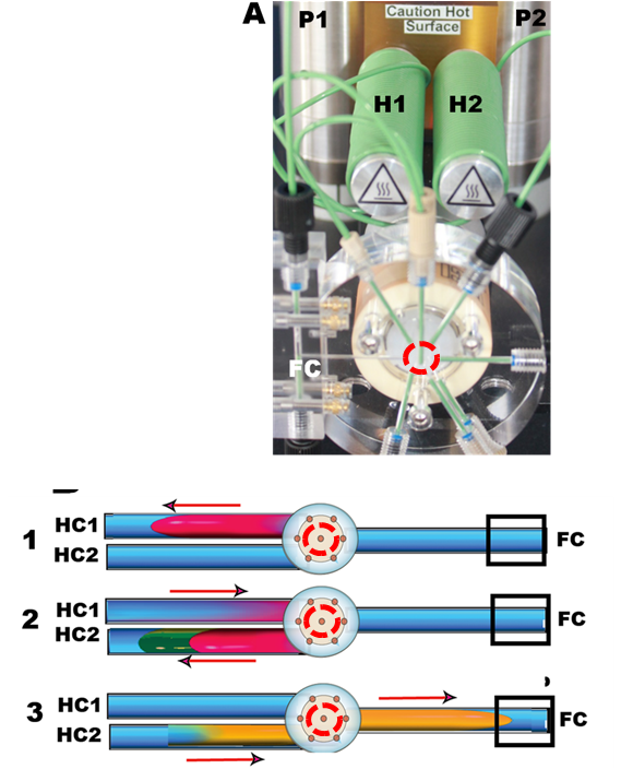
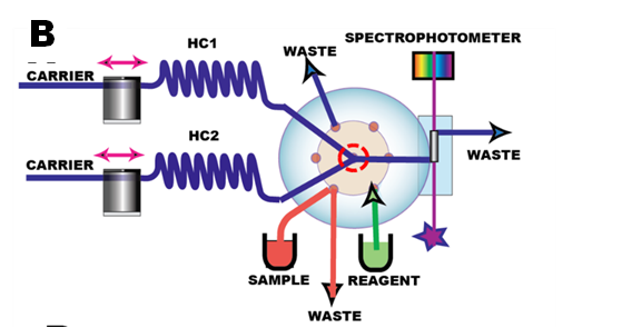
The miniSIA-2 instrument (A) is based on lab-on-valve manifold equipped with two miliGAT pumps (P1,P2), two thermostated holding coils (H1,H2) and an externally mounted flow cell (FC) .
The key component of all Flow Injection systems, the confluence point, situated at the central port of the lab-on-valve module
(red circle A,B,C), connected to the pumps via the two holding coils. Sample merges at this point with reagent forming a homogenous mixture, as shown below.
1.2.25.A.


C
SAMPLE
R
E
A
G
E
N
T
This clip simulates merging of sample with reagent at a confluence point situated at the central port of LOV module. The sequence shows aspiration of 100 microliters of blue indicator dye from sample port into holding coil #1. Next, the valve is turned towards the reagent port ( 0.01 N HCl ), and while 200 microliters solution is aspirated at a rate of 50 microliters/second into HC#2, 100 microliter the blue sample zone is pushed from HC#1 at the flow rate of 25 microliters/second, thus forming 1:1 sample/reagent mixture in holding coil#2. Next valve is turned towards the flow cell, flow is reversed and the yellow, acid form of the dye zone is passed through the flow cell. Finally the system is flushed with a burst of rapid flow.
Note that during the second step: sample and reagent aspiration in 1:1 confluence mode into the holding coil #2, the mixing is incomplete while the dye retreats into the holding coil. However after the flow is reversed, the dye zone emerging from holding coil #2 is fully mixed and completely converted into acid form.